
ULTRASONIC INSPECTION
High-Frequency sound waves are sent out at a material to find material changes. A pulser produces an electrical pulse that causes a piezoelectric transducer to send out a sound wave. Reflected waves are transformed back into electrical signals by the transducer and analyzed. Applications are in thickness gauging and flaw detection.
CONVENTIONAL ULTRASONIC TESTING
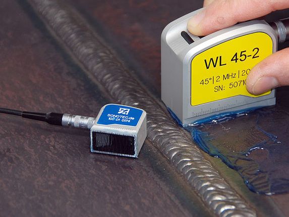
Ultrasonic inspections are largely performed by the pulse echo technique in which a single probe is used to both transmit and receive ultrasound. In addition to the fact that access is required from one surface only, further advantages of this technique are that it gives an indication of the type of defect, its size and its exact location within the item being tested. The major disadvantage is that pulse echo inspection is reliant upon the defects having the correct orientation relative to the beam in order to generate a returning signal to the probe and is not therefore considered fail safe. If the sound pulse hits the flaw at an angle other than 90o much of the energy will be reflected away and not return to the probe with the result that the flaw will not show up on the screen.
Through-transmission was used in the early days of UT and is still used in plate and bar production. A probe one side of a component transmits an ultrasonic pulse to a receptor probe on the other side. The absence of a pulse coming to the receiver indicates a defect.
High-frequency sound waves are sent out at a material to find material changes. A pulser produces an electrical pulse that causes a piezoelectric transducer to send out a sound wave. Reflected waves are transformed back into electrical signals by the transducer and analyzed.Its main applications are in thickness gauging and flaw detection.
ADVANCED ULTRASONIC TESTING
Phased Array (PA) ultrasonics is an advanced method of ultrasonic testing that has applications in Medical imaging and Industrial nondestructive testing. Common applications are to examine the heart noninvasively or to find flaws in manufactured materials such as welds. Single-element (non phased array) probes-known technically as monolithic probes-emit a beam in a fixed direction. To test or interrogate a large volume of material, a conventional probe must generally be physically turned or moved to sweep the beam through the area of interest. In contrast the beam from a phased array probe can be moved electronically, without moving the probe, and can be swept through a wide volume of material at high speed. The beam is controllable because a phased array probe is made up of multiple small elements, each of which can be pulsed individually at a computer-calculated timing. The term phased refers to the timing, and the term array refers to the multiple elements. Phased array ultrasonic testing is based on principles of wave physics that also have applications in fields such as optics and electromagnetic antennae.
The TOFD technique was first applied in 1985 at the Harwell Center (UK) in response to insistent requests to size cracks in nuclear reactor welds. The TOFD technique is a fully computerized system able to scan, store, and evaluate indications in terms of height, length and position with a grade of coverage, accuracy and speed not achieved by other ultrasonic techniques. The TOFD technique is based on diffraction of ultrasonic energy from tips of discontinuities, instead of geometrical reflection on the interface of the discontinuities.
This phenomena makes TOFD effective for identifying cracks and lack of fusion located along the vertical axis of the weld (in particular for narrow gap preparation) or with any other orientations, because defect detection is not affected by unfavourable orientation to the primary sound energy angle. These features have extended the use of TOFD to replace Radiography and complex Ultrasonic inspection by tandem technique wherever planar defects (cracks, lack of fusion) are the main object of examination.
Four different types of waves are involved in the construction of a TOFD image: longitudinal wave generated by the transmitter and partially transformed in spherical wave when the beam crosses the tip of a defect the lateral wave that propagates near the surface between the two transducers .The longitudinal wave reflected by the backwall . The shear waves generated by the mode conversion L/T on the interface of discontinuities
X-RAY
X – Rays are produced whenever high energy electrons suddenly release energy. This can be done either by accelerating electrons to a high speed and then stopping them suddenly or by the high speed electrons striking others and knocking them out of their normal positions. When these dislodged electrons fall back into place they emit X-Rays. X-rays can also be produced by establishing a very high voltage between two electrodes, called the anode and cathode. To prevent arcing, the anode and cathode are located inside a vacuum tube, which is protected by a metal housing. The cathode contains a small filament much the same as in a light bulb. Current is passed through the filament which heats it. The heat causes electrons to be stripped off. The high voltage causes these “free” electrons to be pulled toward a target material (usually made of tungsten) located in the anode. The electrons impact against the target. This impact causes an energy exchange which causes x-rays to be created.